Overview
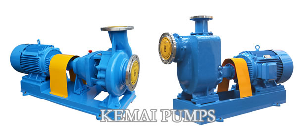
Centrifugal pumps rely on the centrifugal force generated by the rotation of the impeller to deliver the liquid. Divided into end suction and self-priming centrifugal pumps.
Material: cast iron, cast steel, stainless steel, plastic
We usually say that a pump belongs to a multi-stage pump, which refers to the impeller. According to other structural features, it may also be a horizontal pump, a vertical combination surface pump, a guide vane type pump, a high pressure pump, a single-side inlet type pump, and the like. So based on the difference, the name is not the same. In addition, according to the use can also be classified, such as oil transfer pumps, water pumps, condensate pumps, ash pumps, circulating pumps and so on.
What is a centrifugal pump structure?
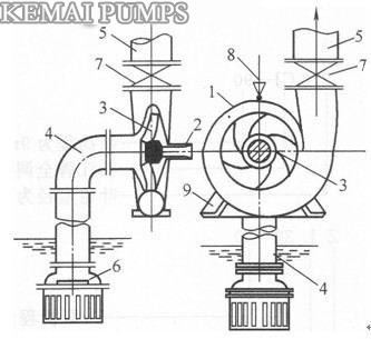
Single stage single suction centrifugal pump structure
1一pump casing;2一pump shaft;3一impeller;4一water inlet ;5一water outlet;6一bottom valve;7一control valves;8一Water funnel;9一pump base
The basic structure of the centrifugal pump is composed of six parts: impeller, pump body, pump shaft, bearing, seal ring and stuffing box.
1. The impeller is the core part of the centrifugal pump. Its rotational speed is high and the blades on the impeller play a major role. The impeller passes the static balance experiment before assembly. The inner and outer surfaces on the impeller are required to be smooth in order to reduce the friction loss of the water flow.
2. The pump body is also called the pump housing and it is the main body of the pump. It plays a supporting and fixing role, and is connected with the bracket that mounts the bearing.
3, the role of the pump shaft is to connect the coupling and the motor, the motor torque transmitted to the impeller, so it is the main component of the transmission of mechanical energy.
4, the use of transparent bearings for lubricants, add fuel to the oil level line. Too much oil must seep out along the pump shaft. Too few bearings must be overheated and burned to cause an accident! The temperature of the bearing during the operation of the pump is up to 85 degrees, and it is generally operated at around 60 degrees.
5, the sealing ring, also known as leakage reduction ring.
6. The stuffing box is mainly composed of packing, water sealing ring, packing tube, packing gland and water sealing tube. The function of the stuffing box is mainly to close the gap between the pump casing and the pump shaft so that the water in the pump does not flow outside and the outside air does not enter the pump. Always keep the vacuum inside the pump! When the friction between the pump shaft and the packing generates heat, it is necessary to rely on the water seal tube to live in the water seal ring to allow the packing to cool! Keep the pump running properly. Therefore, the inspection of the stuffing box during the inspection tour of the pump is of special attention! The packing should be replaced after about 600 hours of operation.
Centrifugal pumps power and efficiency:
The loss of the pump during the operation makes the actual (effective) head and flow of the pump lower than the theoretical value, and the power of the input pump is higher than the theoretical value.
H—The effective head of the pump, ie the amount of energy a unit of liquid receives from the pump in a gravitational field(m);
Q—pump actual flow (m3/s);
ρ—Liquid density(kg/m3);
Ne—Pump effective power,It is the mechanical energy obtained from the pump in the unit time(W)
Effective power can be written as Ne=QHρg
The power input from the motor into the centrifugal pump is called the shaft power of the pump, denoted by N.
The ratio of effective power to shaft power is defined as the total pump efficiency(η),It is η=Ne/N
Centrifugal pump impeller:
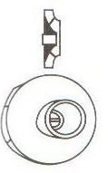 Figure a |
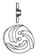 Figure b |
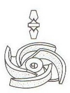 Figure c |
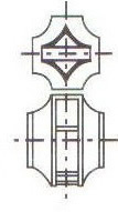 Figure d |
The impeller of the centrifugal pump transmits the energy of the prime mover to the liquid in the pump through the action of centrifugal force, so that the liquid increases the speed and pressure, and the liquid in the pump is discharged, and the liquid in the inlet pipe is sucked in.
Common materials for the impeller are: cast iron HT20~40, HT25~47, cast steel ZG15, ZG25, cast copper ZGCuR, stainless steel 1Cr13, 2Cr13, 1Cr18Ni9Ti, and also aluminum cast iron.
The impeller can be divided into four types according to its structure: in the former form, consisting of the front cover, rear cover, blades and hub, called the closed impeller (Figure a); the second form, from the rear cover , composed of blades and hubs, called semi-open impeller (figure b); third form, composed of blades and hubs, called fully open impeller (figure c); fourth form, 7 by two front covers Consisting of blades, blades and hubs, there are two suction ports distributed on both sides, called double-suction impellers (Figure d).
Semi-open and full-open impellers are commonly used to transport liquids containing more impurities; double-suction impellers are often used in applications with large displacements, good cavitation resistance, and high efficiency.
A list for centrifugal pump classification methods
| Categories | Type | Features |
| According to inhalation | single suction pump | Liquid flows into the impeller from one side and there is an axial force |
| double suction pump | Liquid flows into the impeller from both sides, there is no axial force and the pump flow is almost double that of the single-suction pump. | |
| According to stage | single stage | There is only one impeller on the pump shaft |
| multistage | Multistage pump have two or more impellers are mounted on the same pump shaft, and the liquid flows through each impeller in turn. The more stages, the higher the lift. | |
| According to Pump shaft position | horizontal pump | Shaft placement |
| vertical pump | Shaft is perpendicular to the horizontal plane | |
| According to pump casing type | segmental type pump | Pump casing is mounted on the plane perpendicular to the shaft, with long bolts between the segments and the segments. |
| split-case centrifugal pump | Pump casing is split on a plane passing through the axis | |
| volute pump | fitted with a spiral pressurized water chamber, such as a commonly used end suction cantilever centrifugal pump | |
| turbine type pump | Centrifugal pump with guide vane pressure chamber | |
| special construction | ||
| inline pump | The pump is part of the pipeline and does not need to be changed during installation | |
| immersible pump | pump and motor are integrated into the water | |
| submerged pump | Pump immersed in liquid | |
| shield pump | Impeller is integrated with the rotor of the motor and it is in the same sealed housing. No sealing structure is required and it belongs to a leak-free pump. | |
| magnetic pump | In addition to the inlet and outlet, the pump body is completely closed, and the coupling of the pump and the motor is driven by the mutual attraction of the magnetic steel. | |
| Self-priming pump | No need to fill liquid when starting the pump | |
| high-speed pump | Speed increase of the shaft of the pump shaft is achieved by a speed increase box, and the general speed can reach 10000r/min or more. It can also be called a partial flow pump or a tangential booster pump. | |
| Vertical barrel pump | Pump inlet and outlet take over at the same height, there are two shells inside and outside, the inner shell is composed of rotor, guide vanes, etc. The outer shell is the inlet diversion channel, the liquid is sucked from the lower part. |